Pre-Flight Information
Best Practises for Optimal Flights
PlotVision converts raw aerial images into per-plot image datasets. You can use whichever drone and camera you like, but to facilitate dataset curation, and get the best quality image data, we provide the following recommendations. Before flying, it’s important to understand the limitations and scope of the equipment you’re working with. Often, camera or drone manufacturers will supply guidelines of their own.
In the absence of other guidelines, following the MicaSense guidelines are a good practise. These can be found here, but important points will also be summarized here.
Flight Pattern
Together, the images should cover the whole trial you are flying (no gaps, ideally). Using a standard automated flight plan with regular velocity and periodic image capture will help achieve this.
Between neighbouring images, there must be roughly 80% image overlap on all sides.
When optimizing flight speed vs. capture rate to achieve 80% image overlap, please remember to keep the speed of the drone fairly low, to minimize motion blur (1-2 m/sec is probably ideal).
The flight plan should be set up to go approximately 5 meters past the edges of the trial itself to ensure full coverage.
Images should not be blurry or otherwise low-quality. Try to minimize flight turbulence.
Flight altitude should be as low as can be achieved while fulfilling the other requirements (to maximize image resolution). (15m is fine, but if you can achieve a lower altitude, that is fine too!)
Calibration
It is frequently possible to get good quality metrics without doing much calibration.
But If you desire good quality spectral data (to produce accurate NDVI estimates, etc.), it is important to use a calibration panel with known albedo values for each spectral band
in your camera. You should image this panel at the start of every flight (don’t cast a shadow on the image). You will also have to contact us with information about the model of panel used. - To minimize impacts due to cloudiness, it can help to put the calibration panel on the ground, within sight of the UAV, for the duration of the flight. This might mean moving the panel while the flight is ongoing, but make sure no humans are caught on camera! - If performing multiple missions with the same UAV and sensor setups in the same day, it is recommended to take calibration images at the beginning or end of every mission.
GPS
A GPS mounted on the drone is not necessary, provided you use Ground Control Points (GCPs), but it can help improve results.
If you do mount a GPS, please ensure that one of the following is true:
1. images are either tagged directly with GPS positions (in their EXIF metadata) or 2. there is a drone flight GPS position log, allowing drone timestamps to be matched with image timestamps.
Ground Control Points (GCPs)
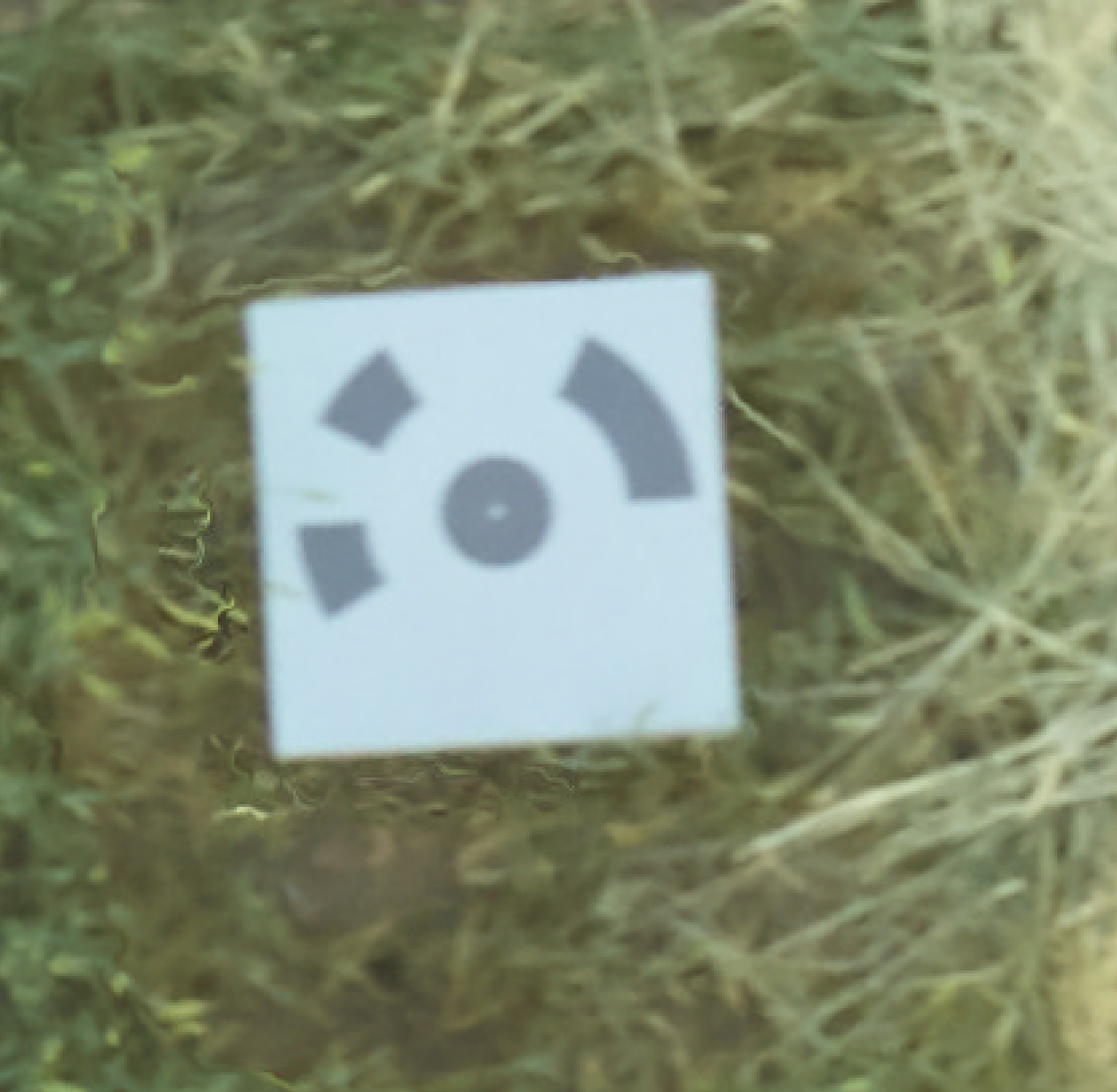
When flying with sensors or UAVs that do not capture accurate or any GPS data, but volumetric measurements of the plots are still desired, then the we recommend the use of Ground Control Points (GCPs). GCPs are also useful in tandem with sensors or UAVs that capture GPS for improved stitching results and accuracy of volumetric measurements. GCPs is the term for physical markers that exist in the field that are RTKed with a GPS point in either Lat/Longs or UTM coordinates. Specific markers designed by Agisoft can be automatically detected and categorized within the images, and will georeference the orthomosaic and DSM of the field.
GCP Markers need to exists permanently in the field, be completely visible and uncovered from a bird eye view, and need to be printed/sized to specific measurements. Each marker in a mission should also be unique, meaning if 12 markers must exist in your field for one orthomosaic, they must be 12 unique markers.
Marker Placement
Select the location for the GCP markers with the following considerations:
You must use at least 4 markers, but more is better.
As a rule of thumb, every point in the trial should be within 30 meters of a GCP. This typically means anywhere from 5-10 GCPs for smaller trials, or 30+ GCPs for very large trials.
The GCP markers should remain in the field for the whole season, as their GPS location will only be recorded once.
The visibility of a GCP should never be impacted during UAV flights. I.e. Make sure that no plants or other objects will be casting shadows on the GCPs during a flight. (If crops are going to grow tall later in the season, try to plan around that.)
GCP Marker Printing
Please contact anyone from the PlotVision team to provide you with PDF or PNG files of markers that can be automatically detected.
For best results, please print them to a size of 24” x 24” (make sure to lock the dimensions if you do resize).
Each PNG has a different pattern, and is identified by a very small ID number in the bottom left corner, or the name of the file.
For a given UAV flight, all imaged GCPs must be a different pattern, with a different ID number. (But different fields can re-use patterns, for instance.)
The PNGs should be printed on weather-resistant material (preferably corrugated plastic).
Recording GCP Location
It is important to record the GPS location of each GCP with good precision.
If mounting GCPs on a year-round basis, it is sufficient to record each GCP’s location only once during the field season.
If placing GCPs on a per-flight basis, make sure to also record the GPS locations each time.
We recommend using a RTK GPS system (precision <= 2cm) for best results, but any GPS measurement is better than nothing.
Please record the precision of your GPS measurements. (e.g. +/- 0.02m)
Please use the attached template CSV file (gcp_template.csv) to fill in your measurements. Note that for ‘target N’, N refers to the ID number printed on the GCP.
If your UAV imaging system also provides GPS measurements (either in a log or directly within image metadata), please ensure that the datum for the UAV matches the datum used for the GCPs. If not using WGS84, please specify the datum used in the ‘datum’ column of your gcp.csv.
Camera/Sensor Types
PlotVision supports many of the standard cameras used for drone imaging. If you use a different camera that does not appear on the list of supported sensors, please shoot us a message, and we’ll see about providing support.
- Supported Sensor Types
Any generic RGB camera
Anything MicaSense
Parrot Sequoia
Sentera NDVI/NDRE/NIR
Hyphen Airphen
PhaseOne and FC350 high resolution cameras
- Recommendations
If you have not yet obtained a camera, but are interested, we have a few recommendations based on your needs. Namely, if you need indices such as NDVI, the MicaSense RedEdge camera will function best with our system, and is relatively inexpensive. The biggest downside is the image quality. If you desire other metrics that perform better with higher resolution, the PhaseOne camera captures at a much higher resolution, but is limited to the RGB colour bands.
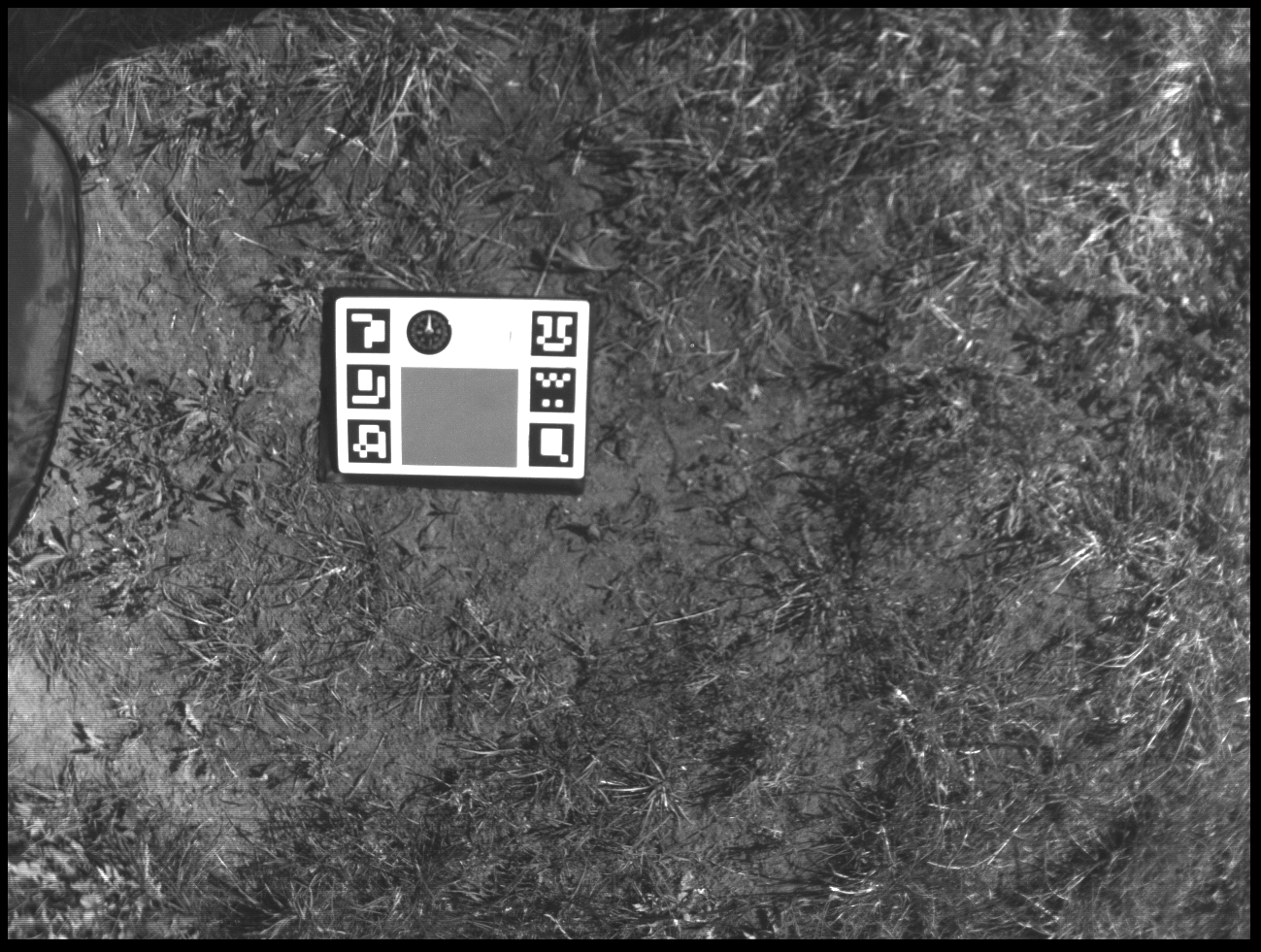
Colour Calibration Panels
The raw colour values taken by a camera can change from one flight to the next, just due to external factors like the sun, cloud cover, or time of day. Colour calibration panels correct for this by normalizing the reflectance values, and make for more accurate comparisons across flights. It is highly recommended that an image of a calibrated reflectance panel be captured before each and every flight.
The standard for calibration panels currently used in PlotVision is the MicaSense panels. Despite being MicaSense brand, they can be used by any sensor, including RGB cameras. If you use another type of calibration panel, please let us know, as it may require some manual input to use other panels correctly.
When capturing a calibration image, the panel should be flat on the ground, away from any objects that can cause odd reflections of light to hit it (such as vehicles, or shade from trees). Also ensure that the actual reflectance panel is in at least 1/3 of the shot, and that any QR codes are also in shot. More information about how to capture a proper calibration image can be found here at the MicaSense website.